|
| |
|
|
|
|
|
|
|
Calibration TheoryPresently, calibration occurs at Marine Physical Lab prior to fielding the instruments. These calibrations are done quite rigorously, so that the limiting accuracy should be the accuracy of the calibration sources. Some of the calibrations perform the primary function of verifying that system performance is up to the quality standard demanded by the nature of the sensing task. A field calibration device is currently in development, to enable calibration of the sensors without removing them from the field. For the application of determining cloud cover, the calibration stability is less critical, because the system uses image ratios, and only relative calibration must be stable or corrected for. The most critical calibration, the dark calibration, is measured in the field as part of the automated data acquisition procedure. The following sections give a brief overview of the types of calibrations which are normally acquired for a WSI. Most of these calibrations are acquired in a calibration facility at MPL with a 2-meter precision calibration bar. The source is a 1000W FEL lamp traceable to NIST. A lambertian reflectance plaque is placed at the 0 point on the bar, and the imager views this plaque. A high accuracy resistance shunt is used to monitor the lamp current, and the power supply automatically adjusts the voltage to maintain fixed current through the lamp. Dark Level vs Exposure:A dark image is an image acquired with the shutter closed, and provides a measure of the dark current, electronic bias, and readout noise. The dark current is pixel-dependent, and is normally subtracted from the measured images in the field. In the lab, the dark image is acquired as a function of shutter exposure in order to characterize camera performance. In the field, a dark image is acquired whenever the exposure changes, so that a current dark image may be subtracted in the near-real-time processing in the field. Dark Level Repeats:Ten to twenty repeat dark images may be acquired at each of two exposures to characterize the spatial vs temporal variance in the dark images. Shutter Calibration:Images of the uniform lambertian reflectance plaque are acquired at short exposure times ranging from 15 msec to 1000 msec, in order to measure the effective shutter opening time. Linearity Calibration vs Exposure:Images
are acquired at exposure times ranging from 15 msec to 3 minutes, in order
to verify system linearity as a function of input exposure time. In some
systems, this calibration is also used to determine whether the sensor
response is linearly related to the radiance, and measure the non-linearities,
if any, so that the data may be corrected for linearity.In the absence
of exposure induced non-linearity, it is redundant with the Radiometric
Linearity calibration, and thus enables a more careful check of system
performance. Even cameras which are considered quite linear for
most purposes may have sufficient non-linearity, to cause significant
errors in the final results, if they are not properly characterized. The
following figure shows the overall linearity of a system advertised to
to have 1/2 degrees linearity. As seen in the first plot, its overall
linearity is quite good, however the second plot shows the resulting error
if the small non-linearities are not corrected for.
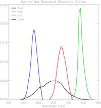
Radiometric Linearity:In this calibration, the distance between the calibration lamp and the reflectance plaque are varied by known amounts on the precision bar, so that the radiance presented to the sensor may be varied by known amounts. This calibration is a used to determine whether the sensor response is linearly related to the radiance, and measure the non-linearities, if any, so that the data may be corrected for linearity. Precision and Uniformity:Twenty images of the reflectance plaque are gathered in quick succession. From these images, a variety of spatial and temporal statistics are determined. These are used to characterize the precision (temporal variance) and the uniformity (spatial, i.e. pixel-to-pixel) variance. Filter Passband Calibrations:In
order to provide absolute radiance, it is necessary to know the effective
lamp irradiance over the passband of the instrument. The passbands for
the D/N WSI are shown here.
In order to determine this, it is necessary to know the lamp spectral
irradiance as a function of wavelength, the CCD sensitivity as a function
of wavelength, and the transmittance of each filter as a function of wavelength.
Lamp and CCD calibrations are provided by the vendors, and the filter
passband calibrations are measured separately. Absolute Radiance Calibrations:Absolute calibrations are acquired for each combination of spectral filter, neutral density filter, and camera gain used in the system. In each filter setting, measurements are acquired at each of five lamp positions. The 5 lamp positions yield five signals for five different radiances. If non-linearities have been corrected for properly, if there are insignificant amounts of stray light, and if the calibration is stable, these five measurements should yield the same calibration constant, in the absence of measurement error. The redundancy in this procedure yields a more accurate determination of the calibration constant, and also enables an evaluation of calibration uncertainty.The results typically show self-consistencies of better than a percent, of the with 0.1% standard deviations. Aperture Calibration:This calibration characterizes the variation in the overall sensitivity as a function of aperture setting. Rolloff Calibration:The rolloff calibration characterizes the variance in overall sensitivity as a function of look angle or angle with respect to the lens normal. This calibration is normally acquired in a 1-meter integrating sphere.It may be further evaluated on the absolute bench, using a rotary table to accurately vary the look angle of the lens, while holding the position of the lens with respect to the plaque fixed. Flat Field Calibration:The flat field calibration is a measure of the variation in pixel sensitivity at each pixel over the whole image. This correction is not required for cloud decision results or image viewing, but is required for the absolute radiance distribution extraction. Together, the dark image and the flat field image may be used to adjust the pixel-to-pixel variations in bias and gain. The WSI presents special difficulty in flat fielding, as a result of some of the characteristics of the fiber optic taper. A unique technique was developed using a 1-meter integrating sphere, and using numerical corrections to remove certain artifacts of the sphere.y
Produced
by the Marine Physical Laboratory, SIO.
developed by Dr. Tim Tooman of Sandia National Labs. Using this technique, we normally obtain angular precisions of .25 degree or better. |